Connectors and Indicators
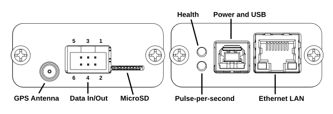
Health
The upper LED indicates the overall health of the GPS receiver and time-of-day data. Green indicates that correct time-of-day is available. Yellow/orange indicates that data is being received from the GPS but the Almanac is not fully downloaded yet so UTC time-of-day is not available. Yellow/orange will also be displayed if the tracking loop is not settled. Red indicates that time-of-day is not being received.
Pulse-per-second
The lower LED flashes in synchronization with the beginning of each second. Its color also indicates the status of the tracking loop. Green indicates that the tracking loop is locked and ready to serve time. Flashing red indicates that pulse-per-second is being received from the GPS receiver but the tracking loop is not yet settled. Steady red indicates that no pulse-per-second is being received.
Power and USB
USB type B receptacle. Used primarily for 5V DC power. If connected to a PC, it enumerates as a serial port which can be used to configure Laureline.
Ethernet LAN
Modular 8p8c (RJ45) receptacle for 100Base-TX Ethernet. Supports auto-negotiation (10 or 100 Mbit, half- or full-duplex) and Auto-MDIX (no crossover cable required). It is highly recommended to use auto-negotiation and not to “force” the switch port to a particular speed as this can cause compatibility problems and packet loss.
GPS Antenna
SMA (normal polarity) receptacle. Connect to a powered or unpowered GPS L1 antenna that supports 5V power. 3.3V power is also possible by changing a solder jumper.
Data In/Out
Multipurpose connector for input and output functions. Can be used to input data and PPS from an external GPS receiver, or to output data and PPS to other equipment. Also supplies a small amount of 3.3V and 5V power or can be used to input 5V power. Connect using an IDC “ribbon” style header. Do not input raw RS232 signals to this header. Data inputs must not exceed 0-5V.
Pinout:
- Ground
- Serial data out - 3.3V CMOS level
- +3.3V power out
- Serial data in - 3.3V-5V CMOS or TTL level
- +5V power in/out
- Pulse-per-second in/out - 3.3V-5V in, or 3.3V out
When the PPS pin is configured as an output, it outputs a buffered, unregistered 3.3V pulse from the GPS module. There is a small series resistor to protect the driver but it is not impedance matched nor can it withstand an indefinite short-circuit. Check compatibility with the equipment you plan to connect. The pulse has a width of 100 ms.
MicroSD
Optional MicroSD card. Must be formatted with a FAT12, FAT16, or FAT32 filesystem. Currently only used for firmware updates but may be used for logging, configuration, and/or diagnostics in the future.
Internal Connectors
P2, P3 - Debug
Serial Wire Debug connection for flashing and debugging the main microcontroller. P2 is a “ST-Link” header without the SWV pin. P3 is a Tag Connect pad for use with the TC2030-CTX-NL cable.
P5 - 5V IN
Alternate power input. Connect 5V DC here as an alternative to powering from USB. This is wired directly to the USB power so connecting both at once could damage your PC and/or your power supply. Mind the polarity, too.
P9 - Battery
Optional RTC backup battery. Use a 3V lithium coin cell or similar, not exceeding 3.3V. If present then the GPS receiver will be able to “warm start” within a few seconds after power is restored. The NTP server will not keep time nor answer queries while unpowered even if the backup battery is connected, and 1-2 minutes of settling time is still required after power-up before NTP is available.